To open the Part Stacker Module, from the Modules interface in the AP100US program click the Edit Stacking button.
Note: If the Stacker module doesn't launch, it may be because this button has been disabled in Preferences>Display options.
The Part Stacker
Module allows the user to clearly view the results of a part removal operation
on the stacking table, and also to re-arrange
the final stacking position of each part.
|
To open the Part Stacker Module, from the Modules interface in the AP100US program click the Edit Stacking button. Note: If the Stacker module doesn't launch, it may be because this button has been disabled in Preferences>Display options. |
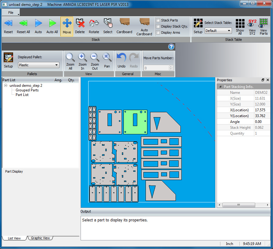
If the parts have been unloaded to the part stacking table in the AP100US Modules work area, when the Part Stacker module opens the parts will appear in that placement as in the image below.
A sheet or job file may also be opened by in the Part Stacker by clicking File>Open and then selecting a file.
| File Menu | General & Misc Menu |
| Stack Menu | Parts List |
| Stack Table Menu | Output Panel |
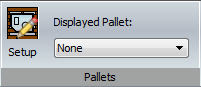
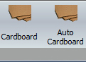
| Pallets Menu | Cardboard Insertion |
| View Menu |
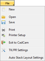
New
Click to open an SY2 file, Sheet file, Job file or Schedule file in the Stacking module. If there is a file currently on the stacking table, the program will ask to clear the data base before proceeding. Click Yes to proceed or No to cancel the operation. If Yes is selected, the Open File window will display; browse to the necessary folder.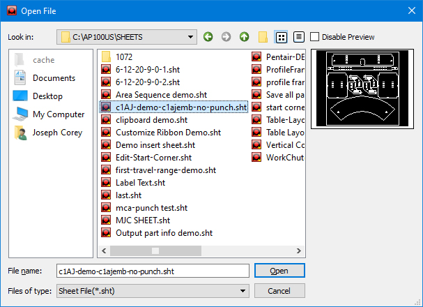
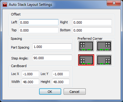
Changes made here become the default until changed
Stack menu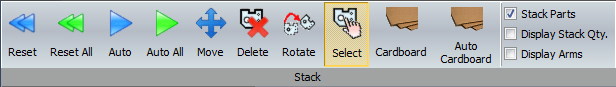
The user may also manually enter values in the X and Y fields that appear in the X / Y location flyout attached to the cursor, or the Location fields found in the part Properties panel. After typing in values, hit <Tab> to enter the value and jump to the next field, or hit <Enter> to confirm the entry, complete the operation and release the part.
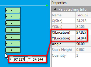
When a part is
selected the X field in the Location flyout
is active; use <Tab> to jump to the Y field and back
Location &
angle can also be selected by
clicking the arrows in an active cell

Stack
Parts
The Stack
Parts checkbox is enabled by default as this is the most likely choice.
This allows the program to stack similar parts at the same angle in one
stack. The height of the stack is controlled by the user-entered value
set in the TK or PR Setting windows. (This
value is passed on from the PSR Settings in
the AP100US program
and saved with the machine file; it is editable in the Stacking Module.)
Uncheck this box to NOT allow similar parts to stack one on top of the other.
Display Stack Quantity 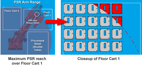
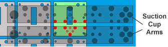
Active suction cups are shown in red
Customizing the assignment and placement of suction cups is possible in AP100US work area. See Modules>Edit Arm and PSR Unloader Settings or TK Unloader Settings for complete info.

|
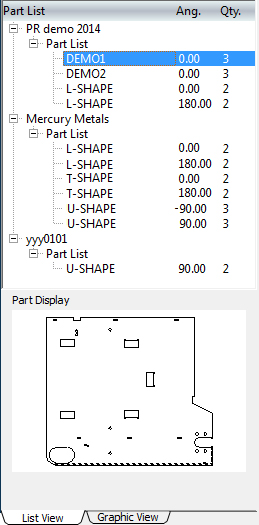
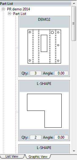
The
Part List shown here lists the sheet files that have been loaded
into the Stacking module, as well as the individual parts in each
of those sheets. When the parts are unloaded onto the stacking
table (either by Auto or manually), the part names will disappear
from this list. Select a part to see a thumbnail in the Part Display. Right-click a part list and click Remove to remove it from this list. |
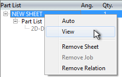 |
Right-click
on a sheet name to open the flyout menu.
Select Auto to auto-unload this sheet to the stacking table in the work area. Clicking View (placing a checkmark) hides the parts in the work area from view. Remove Sheet deletes the sheet from the Part List. If a job file has been opened, click Remove Job to delete it from the list. If a schedule file from Sheet Wizard that contains two or more sheets has been opened, click Remove Relation to remove that sheet from the schedule file, allowing it to be edited separately. |
The user may also left-click
a part (or part kit) in the Part List
and drag it onto the stacking table, left-clicking again to place it.
Coordinate values can be directly entered into the X
and Y flyout fields that are attached
to the cursor. After typing in values,
hit <Tab> to enter the value
and jump to the next field, or hit <Enter>
to confirm, complete the operation and release the cursor.
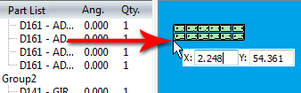
Note: When entering values here if the user does not hit <Enter>, the cursor will remain attached to the part, prohibiting any further action.
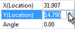
The
padlocks in the image below indicate that the user has typed in values
in the first and second fields and has hit <Tab>
after
each entry. When <Tab> is
hit after an entry 1) the part jumps to the new location, 2) the value
is "Locked" in that field and 3) the
cursor will jump to the next available field. At this point the cursor
will still remain attached to the part, preventing further user input.
The user must then hit <Enter>
to release the part. When
typing in values in either the flyout (shown here) or in the Properties
panel,
hitting <Enter> will complete the action.
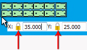
Padlocks indicate that
the field has been locked
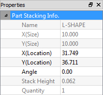
When a part is selected a
Properties panel for that part
opens on the right side of the work area, showing absolute values for
the part.
Enter Location and Angle values and after typing in values hit <Tab> to enter the value and jump
to the next field, or hit <Enter>
to
complete the operation. All other fields in the Properties panel are read-only.
When the cursor hovers
over a part stack,
the Stack Height will display in a flyout
attached to the
cursor
When the Graphic View tab is clicked, a graphic view of the parts with read-only info displays for parts in a selected sheet.
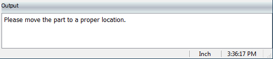
The
Output panel at the bottom of
the work area gives basic instructions and results for the user.
It also has an Inch/Metric toggle
that applies to all values in the program.