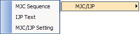
The option MJC/IJP
is found in the Modules menu. There are three options:
MJC Sequence, IJP Text and MJC/IJP Setting. |
|
Option |
Description |
MJC Sequence |
Defines the sequence the machine will use
to cut the microjoints. |
IJP Text |
Print characters on the part(s) or sheet(s). |
MJC/IJP Setting |
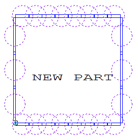
Place the microjoint cut flags and the text
on the sheet. |
Notes: |
1. |
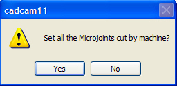
A message will prompt you
to select the MJC when selecting Apply in the Punching
Microjoints menu (Machine\Edit Material). The system
will generate the microjoints automatically according to the settings
in the Punching Microjoints panel when selecting Yes. |
|
|
2. |
You can add the microjoints
cut by the MJC machine manually using the Place Microjoint
option (Sequence Features/Punch Microjoint). |
3. |
The machine driver must
support the MJC function, or the MJC section in the Microjoint
properties window will be absent. |
|
|
|
Option |
Description |
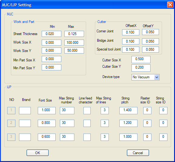
MJC |
Micro Joint Cutter |
Work and Part |
|
Sheet Thickness |
Specifies the thickness range for MJC cutting.
(Default Value: Min = 0.4, Max = 3.2.) |
Work Size X |
Specifies the work size for MJC cutting
in the X direction. (Default Value: Min X = 900, Max X = 2500.) |
Work Size Y |
Specifies the work size for MJC cutting
in the Y direction. (Default Value: Min Y = 900 and Max Y = 1250.) |
Min Part Size X |
Specifies the minimum part size for MJC
cutting in the X direction. (Default Value: X = 120.) |
Min Part Size Y |
Specifies the minimum part size for MJC
cutting in the Y direction. (Default Value: Y = 50.) |
|
Note: the part size is calculated
according to the overall rectangular size. |
Cutter |
|
Corner Joint |
Specifies the offset value of the MJC cutting
coordinate. The range can be set from 0.0 to 9999.9999. The offset
value is added according to the coordinate. If the cutter rotates,
the coordinate axis will also rotate (Default Value: X = 0.0,
Y = 0.0.) |
Bridge Joint |
This is the same as a microjoint. (Default
Value: X= 0.0 Y= 0.0.) |
Special Tool Joint |
This is the same as a microjoint. (Default
Value: X= 0.0 Y= 0.0.) |
Cutter Size X |
Specifies the horizontal cutter size. The
cutter is inserted into the hole that has been punched out. Defines
the hole for the MJC cutting coordinate in the X direction. (Default
value: X = 30.0.) |
Cutter Size Y |
Specifies the vertical cutter size. The
cutter is inserted into the hole that has been punched out. Defines
the hole for the MJC cutting coordinate in the Y direction. (Default
value: Y = 5.0.) |
Device Type |
This is the device type: No Vacuum/Vacuum.
(Default Value: X = 0.0 Y = 0.0.) |
IJP |
Ink Jet Printer |
No |
This is the flow number. |
Brand |
The manufacturer of the IJP device. H =
Hitachi, U = Union. |
Font Size |
The size of the font. |
Max String Number |
Specifies the maximum number of characters
that can printed. |
Line Feed Character |
Specifies the line-feed code used in printing
several character strings. |
Max String of Lines |
Specifies the maximum number of lines that
can be printed. |
String Pitch |
Specifies the pitch for the character strings. |
Raster Size ID |
Character size information that is sent
to the IJP. The printer will use the raster size and string size
information to determine the actual character size and pitch when
printing. (This is used to draw the interference. Check with the
hole during simulation. The actual character size is determined
by this information.) |
String Size ID |
This is the character size ID that is sent
to the IJP. |
OK |
Applies the settings to the current session. |
Cancel |
Exits without saving the changes. |
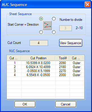
You
must define the MJC sequence after specifying the parameters.
Select MJC Sequence from the MJC/IJP submenu. The
options in this window allow you to define the parameters for
the micro-joint cutting. |
|
Option |
Description |
Sheet
Sequence |
Define the sheet sequence
for microjoint cutting. |
Start
Corner + Direction |
The radio buttons represent
the actual starting corner: Upper Left, Upper Right, Lower Left
or Lower Right. The button in the center functions as a toggle,
allowing you to specify the direction. |
Number
to Divide |
Set numbers of divided sections. |
Cut
Count |
Indicates the number of microjoints
to be cut. |
View
Sequence |
Select to view the sequence. |
MJC
Sequence |
Specifies the part processing
sequence. |
Cut
Sequence |
The cut sequence of the microjoint
on the sheet. |
Cut
Position |
The actual coordinates of
the microjoint. |
Tool
# |
The station number containing
the cutter tool. |
Cut
Type |
The type of cut. |
OK |
Applies the settings to the
current session. |
Cancel |
Exits without saving any
changes. |
Defining the text printed
on the part(s) involves selecting the field codes used to print
specific information on them. For example, if selecting the field
code that represents the Part File Name, the system will
print the name of the actual CAD file on the part. |
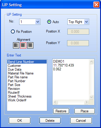
Select IJP Text from
the MJC/IJP submenu in order to define the text. The IJP
Setting window will appear. The options in this window allow
you to select which information you want printed on the part(s). |
|
Option |
Description |
IJP Setting |
|
No |
Select a machine number (No) from
the drop-down list: 1-3. |
Auto |
The system automatically places the text
according to your selection from the drop-down list: Top Right,
Top Left, Bottom Right or Bottom Left. |
Fix Position |
Specifies the exact position by typing coordinates
in the Position X and Position Y text boxes. |
Position X |
This option only becomes available if you
select Fix Position. (This is the IJP position in X direction.) |
Position Y |
This option only becomes available if you
select Fix Position. (This is the IJP position in Y direction.) |
Alignment |
Left, Center and Right alignment buttons
allow you to specify the origin output for the text. |
Left |
The text will be placed with the origin
output relative to the left. |
Center |
The text will be placed with the origin
output relative to the center. |
Right |
The text will be placed with the origin
output relative to the right. |
Enter Text |
The two lists in this section allow you
to select the text that will be placed on the part(s). |
Text List |
Double-click an item in the list to add
content to the Text Box on the right. |
Text Box |
Type the text that you want to print on
the part(s). |
Restore |
Recall any text previously typed in the
Text Box. |
Place |
Place the text on the part automatically
according to the Auto or Fix Position settings. |
OK |
Applies the settings to the current session. |
Delete |
Removes the text from the part. |
Cancel |
Exits without placing the text on the part. |